« Back to Wireless InSite Features
Outputs
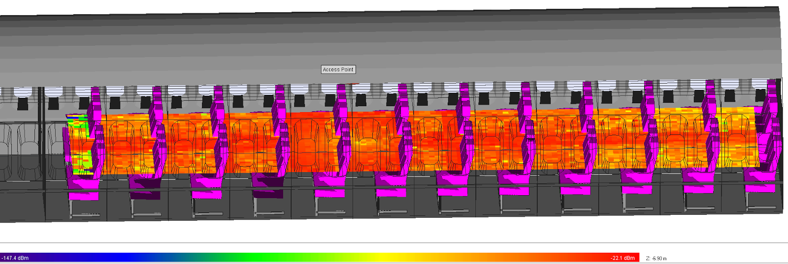
Using Wireless InSite's options for placing receiver points within a scenario, it is easy to generate coverage map displays in the software's project view. Coverage maps can be made for received power, path loss/gain, E-field magnitude, mean time of arrival, delay spread, and many other outputs. The scale bar offers continuous and discrete options as well as control over the display range, values to display, and opacity.
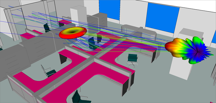
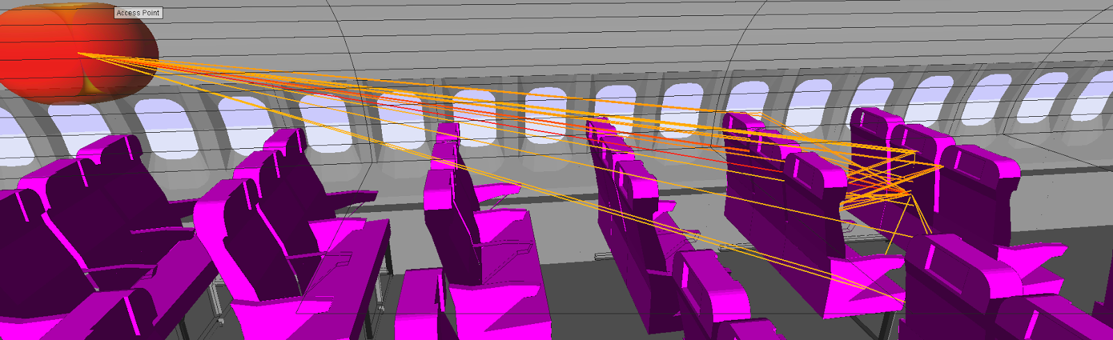
The physics-based propagation models are able to predict the paths by which energy travels from the transmitting to the receiving antenna. Propagation paths through doors and windows, reflection from, and transmission through walls can be easily visualized in the graphical interface.
Wireless InSite writes out and saves output files in ASCII format for quick post-processing. The path information is written out in an SQLite database along with MIMO outputs to CSV files.
An example list of outputs include:
Received power (also for MIMO)
Path loss
Propagation paths
E-field magnitude and phase
Time- and Direction-of-Arrival
Complex Impulse Response (also for MIMO)
Delay Spread
Angle of Departure and Arrival (also for MIMO)
H-matrix (MIMO only)
Maximum Permissible Exposure (MPE)
Wireless InSite’s Maximum Permissible Exposure (MPE) module provides the ability to calculate MPE values and compare them to the safety thresholds defined by the IEEE Standard C95.1-2005. The user may conduct a hazard assessment and visually display the MPE relevant quantities, as well as their relation to the MPE thresholds. This capability allows for both stationary and moving transmitters, multi-pulse waveforms, and includes the aggregation of exposure over time. MPE outputs are currently only available from the X3D propagation model.
Communication Systems
Bit-error rate (BER) outputs are generated for each Tx/Rx pair in the system for LTE, WiMAX, and WiFi protocols. If more than one Tx is active in the system, a combined BER is created.
Data for multiple transmitters are also available, including C/I and strongest base to receiver. All predictions are made with full frequency, polarization, and antenna pattern data taken into account.
An example list of outputs include:
Throughput
Carrier to Interferer Ratio
Receivers Strongest Transmitter
Receivers Strongest Transmitter Power
Receivers Total Power