


This example illustrates how the geometric modeling and electromagnetic calculation capabilities of XFdtd (Release 6) can be applied to antennas on large vehicles.
Airfield Technology was faced with the challenge of locating Flight Inspection System antennas on an unusual aircraft. The Flight Inspection mission places demanding requirements on aircraft antenna performance that can be difficult to meet even with typical aircraft. Airfield Technology was supplying a new Flight Inspection System to the Polish Air Force, which expressed a preference to use a Mielec M-28 aircraft. This aircraft is shown in Figure 1. The dual-vertical stabilizers of the M-28 presented an unusual configuration for a Flight Inspection aircraft and its effect on antenna performance was unknown.
Faced with this challenge, Airfield Technology contacted a well-known expert on numerical electromagnetic methods and their applications in avionics and antenna systems performance, Professor Kent Chamberlin of the University of New Hampshire. Professor Chamberlin referred Airfield Technology to Remcom and XFdtd EM Simulation Software and was a consultant on the study.
Applying XFdtd to this project started with importing a partial CAD file of the M-28 into the software, revising the CAD file to add missing parts, and adding different antennas in various positions. XFdtd was then used for calculating the aircraft skin currents and 2D and 3D antenna patterns. The XFdtd results were used to determine the best antenna type/location combination which would satisfy the antenna coverage requirements.
Importing and Editing the M-28 Aircraft Model in XFdtd
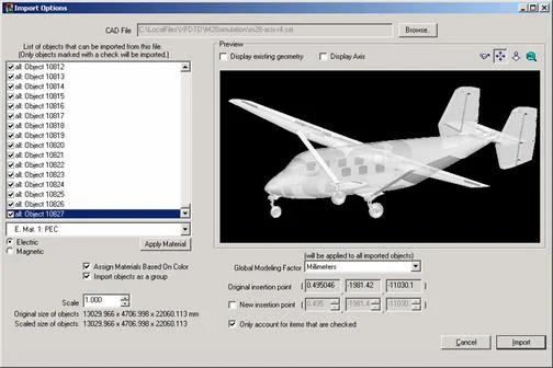
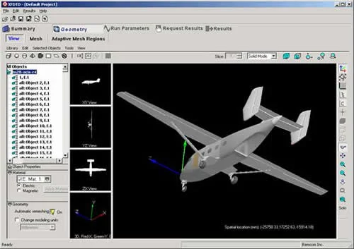
The M-28 analysis started with a CAD file that was provided by the aircraft manufacturer. The CAD file included most of the aircraft geometry. Figure 2 shows the CAD file in the XFdtd import window. This particular CAD model of the M28 contains 10,827 objects in a file about 150 MB in size. The import result is shown in Figure 3.
After importing the M28 geometry into XFdtd, it became clear the CAD file supplied did not describe the complete aircraft. The model lacked a rear hatch and the engines and propellers were absent. Using XFdtd geometric primitives and Boolean operations, the missing components were added to the aircraft.
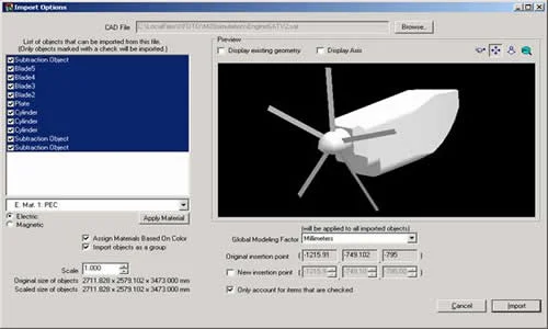
Based on drawings of the engines, CAD models of the engines were created using the XFdtd geometrical modeler. First a single engine model was created and saved as a CAD file in SAT format. The SAT engine model could then be imported back into XFdtd. The engine geometry was imported twice and positioned on each wing. Also, the tires were changed to a non-conductive dielectric approximating rubber. The process is shown in Figures 2-5. Now all that remained was to add antennas to the model and run the XFdtd simulations.
Calculating Antenna Performance for the M-28 Aircraft Using XFdtd
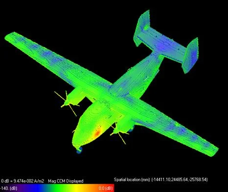
Once the aircraft model was ready, the M-28 analysis continued with placement of antennas on the aircraft. The study involved two different antenna types, a balanced half-loop antenna called a 'towel bar' and a bent dipole V-shaped antenna. Two of the half-loop antennas can be seen on the side of the aircraft in the first figure. These antennas are installed in pairs on each side of the aircraft and phased to provide symmetrical antenna patterns when fed together. The bent dipole antennas are located on the aircraft centerline.
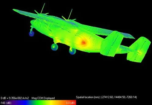
The initial phase of the analysis involved placing these antennas at various locations on the aircraft and calculating the far zone 2D and 3D antenna patterns. From the results of these calculations, candidate antenna types and positions were chosen. Then for these candidate positions XFdtd was used to investigate position sensitivity and frequency sensitivity in order to determine how robust the candidate design would be in the field. Aircraft skin currents were also calculated and displayed to indicate the interactions of the aircraft, especially the large vertical stabilizers, with the antenna radiation.
As with the aircraft engines, the XFdtd geometric modeler was used to generate the half-loop and bent dipole antenna geometries. These were then exported to CAD files, then imported and positioned on the XFdtd aircraft model for calculation.
As a baseline comparison, a few calculations were made for a C-130 aircraft. This aircraft has a single vertical stabilizer and poses no difficulties in obtaining the desired omnidirectional azimuth pattern. As with the M-28, a CAD model of a C-130 was obtained and imported into XFdtd. A half-loop antenna was located on the vertical stabilizer and azimuth plane antenna radiation patterns were calculated using XFdtd. Figure 6 shows the electric field in the plane of the antenna.
Figure 7 shows the skin currents on the C-130 aircraft.
Figure 8 shows the azimuth plane radiation pattern. Notice the very uniform coverage for the Phi (horizontal) polarization, which is of primary importance for flight inspection operations.
Next are shown a few selected results from the M-28 aircraft study. The first configuration is a pair of balanced loop antennas located on the rear fuselage of the M-28 aircraft. The aircraft skin currents are shown as well as the azimuth plane radiation pattern for this antenna configuration. The performance is not acceptable due to the variations in antenna gain, especially in the forward direction.
Several other positions for balanced loop antennas were tried, but none gave an acceptable radiation pattern over the entire azimuth plane. A midship location was tried but still had a significant reduction in gain in the forward direction.
Next the towel bar antennas were located further forward; the azimuth plane pattern for this configuration provides adequate coverage forward but unacceptable nulls remain in the pattern.
Other positions for balanced loop antenna locations, including on the vertical stabilizers, were tried but without providing a uniform azimuth plane pattern. Next a bent dipole antenna was placed at the top of the fuselage. This antenna provides excellent coverage forward but poor coverage to the side and rear.
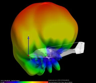
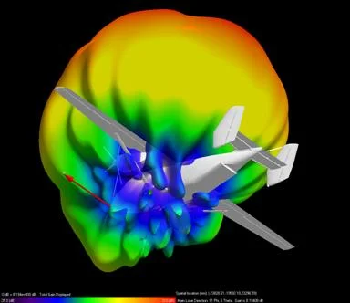
In addition to the azimuth plane antenna pattern plots XFdtd provided 3D patterns as well. These provided a more general view of the radiation from the various antennas.
Only a few of the many results provided by XFdtd for this study are shown here, but enough to indicate the final solution. Airfield Technology installed both the bent dipole and rear-fuselage balanced loop antennas in a switched configuration. The bent dipole is used when the aircraft is flying toward the air navigation system, and the balanced loop used for outbound patterns and during orbital flight patterns when the aircraft flies in a circle around the air navigation system. Airfield Technology configured the airborne equipment so that the Flight Inspection System computer automatically selects the correct antenna for the type of pattern being flown.
XFdtd allowed potential problems with the antenna performance to be identified and solved prior to installing the actual antennas on the aircraft, ultimately saving the customer significant time and money.