« Back to 5G and MIMO Simulation
MIMO and Array Design for 5G
Antenna engineers favor advanced antenna systems capable of beam steering and multiple data stream transmission in order to meet 5G throughput requirements. Designing such a device is a difficult task because many factors are involved in a device’s performance:
Antenna coupling within a device’s case
Effects of multipath propagation
Data transfer schemes
XFdtd and Wireless InSite ensure a comprehensive device design process, from simulating the initial antenna pattern to computing throughput performance in a multipath channel model. Together the products ensure a device will work well in its intended environment.
Four possible beams for a 28 GHz array
Stand-Alone Device Performance with XFdtd
Laptop with a four element MIMO antenna
Remcom’s time-domain electromagnetic simulation software, XFdtd, enables in-depth analysis of a device’s stand-alone performance. Detailed CAD models of the antennas, PCB, and device assembly are imported from Pro Engineer, Allegro, and other software packages. The following results are available from a single finite-difference time-domain (FDTD) simulation:
Antenna isolation
Envelope correlation
Antenna efficiency
Antenna patterns
An RF engineer needs to go beyond stand-alone antenna performance in order to ensure sufficient 5G device performance. Results from an XFdtd simulation that characterize the performance of an antenna are easily exported to Wireless InSite where the device is analyzed in its intended environment.
For additional resources, visit our XFdtd for 5G Device Design page...
Exporting Antenna Data for Channel Simulations
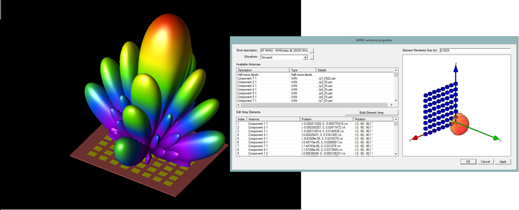
Channel simulations provide a means to predict how systems will perform within a realistic setting, such as a connected home, indoor office environment, or an outdoor urban or suburban scene. Realism for this type of analysis is considerably improved by including the key characteristics of a device’s antennas as predicted by XFdtd. To facilitate this, XFdtd can export the following types of antenna data:
3D antenna radiation patterns, including:
Unique pattern for each element of MIMO antenna
Frequency-specific patterns
MIMO antenna element layouts
MIMO codebooks
MIMO multi-port S-parameters
For MIMO systems, the 3D layouts can be exported so that the full physical definition of an antenna or array can be directly imported. In addition, optimization scripts can create custom codebooks, and multi-port S-parameters can be used to incorporate the impact of mutual coupling on performance analysis.
Antenna element patterns and relative positions can be exported from XFdtd and loaded into Wireless InSite for channel simulations
Simulating the 3D Multipath Channel
Office layout with access point (AP) and single laptop location
3D propagation scenarios can be modeled in Remcom’s wireless prediction software, Wireless InSite. Site-specific and generic test environments are created by importing terrain, defining building floor plans, specifying base station or access point locations, and providing material information. MIMO antenna designs from XFdtd are then tested in applications including:
City blocks for small cell base station deployment
Outdoor-to-indoor for fixed wireless access scenarios
Office buildings for WiFi access planning
Location of AP in corner of office
Wireless InSite uses high-fidelity ray-tracing models to determine multipath propagation through the 3D environment. These industry leading capabilities include the ability to analyze:
3D terrain, buildings, and floor plans
Fine structural details including curbs, window frames, chairs, and desks
Diffuse scattering at millimeter waves
Attenuation from trees, shrubs, and other foliage
Propagation paths between AP and single laptop location
Transmitters and receivers are comprised of one or more antenna elements. Wireless InSite computes the link between each antenna element on the transmitter and receiver and reports results including:
Complex impulse response at each receiver
Received power
Coverage maps
Power delay profiles
H-matrices connecting each antenna element on a base station or access point to those on a UE or device
Once the 3D propagation scenario has been characterized, communication systems can be overlayed to determine throughput and capacity metrics.
MIMO and Communication System Analysis
Given the MIMO antenna design and 3D channel characteristics, Wireless InSite’s Communication Systems Analyzer allows the RF engineer to evaluate a 5G device’s operation in the intended scenario.
Throughput coverage for all laptop locations
To start, a MIMO technique is applied to each transmitter and receiver. This will improve a system’s performance by increasing the signal-to-interference-plus-noise ratio (SINR), providing multiple parallel data streams, or both. Wireless InSite models the following MIMO techniques:
Antenna diversity
Spatial multiplexing
Beamforming
MIMO techniques determine how data is transmitted through the 3D environment. Once that is known, Wireless InSite determines how much data can be transmitted. The following metrics are accessed for each data stream and point-to-point link:
Throughput and capacity
Bit error rate (BER)
Noise, interference, and SINR
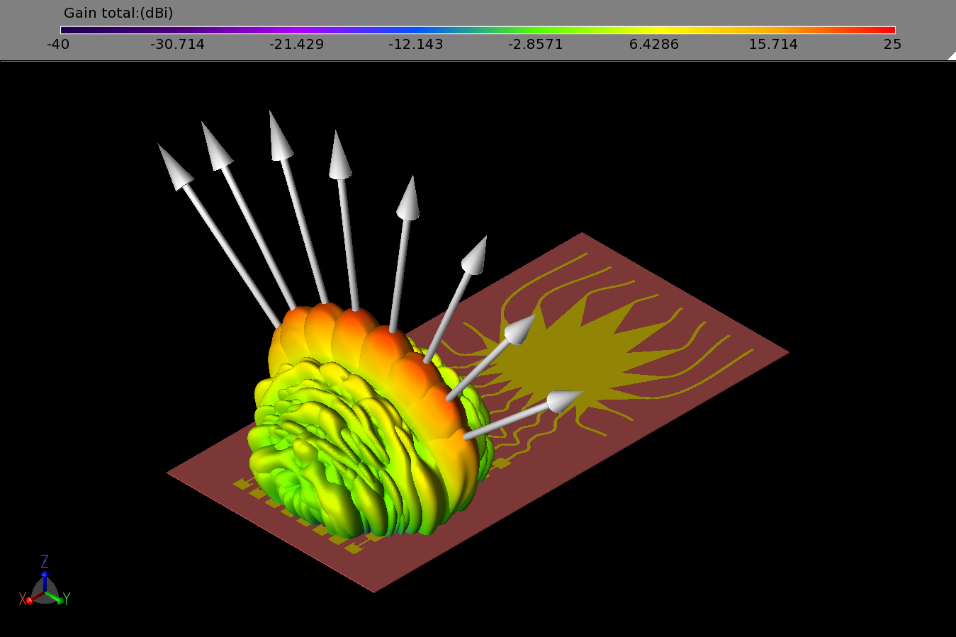
Example showing how mutual coupling can degrade MIMO beamforming, if sufficiently strong and not compensated for in codebook weighting coefficients.
This results in a powerful tool that engineers use to determine if their device will meet 5G performance requirements in a realistic operating environment.
When multi-port S-parameters are imported from measurement data or full-wave simulations, the analysis can capture the impact of mutual coupling between MIMO elements. MIMO systems rely on channels that are uncorrelated, so mutual coupling can degrade the performance of MIMO techniques like spatial multiplexing, which aims to generate orthogonal data streams. It can also degrade MIMO beamforming if codebook weights are not tuned to compensate for it, as shown in the figure to the right. During the MIMO analysis, the S-parameters are applied to capture the effect of mutual coupling in the channel matrix, and later analysis will then incorporate this effect in the predicted performance in terms of SINR and throughput.
Additional Information
Examples


Publications


Webinars

Videos