Frequency-Domain Circuit Solver and Schematic Editor
Build a matching network or corporate feed network and see its impact on full-wave results.
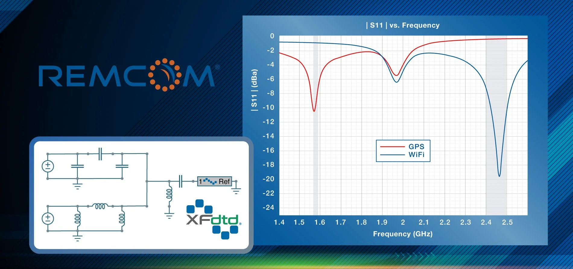
XF includes a schematic editor specially designed for antenna engineers who need to analyze matching networks and corporate feed networks. The S-parameters from an FDTD simulation are readily accessible for analysis. The associated frequency-domain circuit solver quickly solves the circuit layout and provides matched results. Once the matching network or corporate feed network analysis is complete, the schematic can be applied to the FDTD simulation where full-wave results can be inspected.
Supported components:
Resistors
Ideal and lossy inductors
Ideal and lossy capacitors
Switches
Phase shifters
Netlist file import
SnP file import
FDTD block
Voltmeter
Ammeter
Ideal transmission line
Microstrip transmission line, tee, bend, step
Coplanar and grounded coplanar waveguides
The schematic editor includes an analysis workbench that provides sliders for tuning. Tuning is used to determine component values that meet performance metrics. It also allows users to see how a matching network’s behavior varies with each individual component.
In addition to the standard components listed above, XF’s schematic editor allows users to seamlessly specify operating modes and multi-state devices.
When a schematic is applied to an FDTD simulation, the following steady-state full-wave results will update:
Port data including S-parameters, VSWR
System and radiation efficiencies
Available, input, dissipated, and radiated powers
Near field sensors
Far field sensors
Additional Information
Press Releases

Webinars


Videos


